

DRV8908QPWPRQ1 Motor Driver Datasheet,Pinout,Specification
yunying Release time:2024-05-07 Page View:424
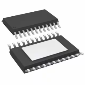
DRV8908QPWPRQ1 AUTO MULTI-CHANNEL Drivers Automotive 40-V, 6-A, 8-channel half-bridge motor driver with advance diagnostics 24-HTSSOP -40 to 125
The DRV8908QPWPRQ1 is a motor driver that provides efficient and reliable control for various motor applications. It is commonly used in automotive and industrial systems to ensure high performance. In this article, we will explore the features and functions of the DRV8908QPWPRQ1 and provide an overview of its pinout configuration. We will also discuss where to find the DRV8908QPWPRQ1 datasheet for more detailed technical information.
What is DRV8908QPWPRQ1?
Overview of the DRV8908QPWPRQ1
The DRV8908QPWPRQ1 is a motor driver that helps control brushed DC motors, stepper motors, and solenoids. It can handle a wide range of motor types and is designed specifically for automotive and industrial applications. The motor driver works with a supply voltage between 6V and 45V, providing a flexible and feature-rich solution.
DRV8908QPWPRQ1 Pinout

DRV8908QPWPRQ1 Pinout


Pin Description
The DRV8908QPWPRQ1 comes in a 28-pin HTSSOP package. Here is a simplified explanation of its pinout configuration:
1. VCP: Charge pump output for the high-side gate driver.
2. VCPGND: Ground connection for the charge pump.
3. CP1: Connection for the bootstrap capacitor of high-side gate driver 1.
4. CP2: Connection for the bootstrap capacitor of high-side gate driver 2.
5. OUT1: Output for motor 1.
6. OUT2: Output for motor 2.
7. VCP2: Second charge pump output for high-side gate driver.
8. VCPGND2: Ground connection for the second charge pump.
9. CP3: Connection for the bootstrap capacitor of high-side gate driver 3.
10. CP4: Connection for the bootstrap capacitor of high-side gate driver 4.
11. OUT3: Output for motor 3.
12. OUT4: Output for motor 4.
13. VREF: Reference voltage output.
14. VCP3: Third charge pump output for high-side gate driver.
15. VCPGND3: Ground connection for the third charge pump.
16. CP5: Connection for the bootstrap capacitor of high-side gate driver 5.
17. CP6: Connection for the bootstrap capacitor of high-side gate driver 6.
18. OUT5: Output for motor 5.
19. OUT6: Output for motor 6.
20. VREF2: Second reference voltage output.
21. GND: Ground connection.
22. VCC: Supply voltage input.
23. VCP4: Fourth charge pump output for high-side gate driver.
24. VCPGND4: Ground connection for the fourth charge pump.
25. NC: No connection (leave unconnected).
26. ENBL: Input to enable or disable the motor driver.
27. MODE: Input to select the operating mode of the device.
28. VSENSE: Output for the current sense voltage.
CAD-Model
symbol

footprint

3d-model

DRV8908QPWPRQ1 Datasheet
For detailed technical information about the DRV8908QPWPRQ1, such as electrical characteristics, recommended operating conditions, and application guidelines, you can refer to the official datasheet. The datasheet contains comprehensive information about the device's pin functions, block diagrams, timing diagrams, and application schematics. You can find the DRV8908QPWPRQ1 datasheet by swiping to the end of the article at Xinshop website or through various electronics component distributors Xinshop Electronics.
Key Features
Here are the DRV8908QPWPRQ1 Features:
1. High-performance motor driver: The DRV8908QPWPRQ1 is designed to drive brushed DC motors and can handle motor currents up to 7A, making it suitable for a wide range of motor control applications.
2. H-Bridge configuration: It incorporates an H-bridge motor driver configuration, allowing bi-directional control of the motor rotation.
3. Integrated protection features: The IC includes various protection features such as overcurrent protection, over-temperature protection, and undervoltage lockout, which help safeguard the motor and the driver circuitry.
4. PWM control: It supports pulse-width modulation (PWM) control, enabling precise speed and torque control of the motor.
5. Wide operating voltage range: The DRV8908QPWPRQ1 can operate from a wide voltage range, typically between 8V and 60V, allowing flexibility in motor supply voltage selection.
6. High Peak Current: The DRV8908QPWPRQ1 can deliver a strong peak output current of up to 2.2 A, making it suitable for various motors.
7. Integrated MOSFETs: This motor driver includes built-in power MOSFETs, which simplifies the design and reduces the need for external components.
8. Adjustable Current Control: The DRV8908QPWPRQ1 allows you to adjust the current control settings, giving you precise control over the motor's speed and torque.
Applications & Alternatives
The DRV8908QPWPRQ1 can be used in various applications that require the control of brushed DC motors, such as robotics, industrial automation, home appliances, automotive systems, and more. It provides a compact and integrated solution for motor control, reducing the need for external components.
There are alternative motor driver ICs available from different manufacturers that serve similar purposes. Some alternatives to the DRV8908QPWPRQ1 include the DRV8871, L293D, and L6203, among others. The choice of an alternative depends on factors such as specific application requirements, desired performance, cost, and availability.
Functional Block Diagram
The functional block diagram of the DRV8908QPWPRQ1 typically includes input pins for motor control signals, power supply pins for the motor and control circuitry, H-bridge driver circuitry, protection circuitry, and diagnostic outputs. The exact details can be found in the device datasheet provided by Texas Instruments.


Simplified Schematic
How to use DRV8908QPWPRQ1
To use the DRV8908QPWPRQ1, you generally need to follow these steps:
1. Power supply: Provide the appropriate power supply voltage within the specified operating range to the designated power pins of the IC.
2. Motor connections: Connect the motor terminals to the appropriate pins of the driver IC, considering the motor polarity and the H-bridge configuration.
3. Control signals: Connect the control signals (such as PWM or direction signals) to the designated input pins of the IC for controlling the motor speed and direction.
4. Protection and diagnostic features: If needed, you can utilize the diagnostic outputs and protection features of the IC by connecting the corresponding pins to the control or monitoring circuitry.
5. PCB layout and thermal considerations: Follow the guidelines provided in the datasheet for proper PCB layout and thermal management to ensure reliable operation and prevent overheating.
How DRV8908QPWPRQ1 works
The DRV8908QPWPRQ1 utilizes an H-bridge configuration to control the direction and speed of a brushed DC motor. The H-bridge consists of four power switches (typically MOSFETs) that can be driven in various combinations to control the current flow through the motor windings.
By applying appropriate control signals to the driver IC, you can toggle the power switches to provide the desired current path through the motor. The DRV8908QPWPRQ1 interprets the control signals and generates the necessary gate drive signals to turn on/off the power switches accordingly.
The PWM control input allows you to modulate the duty cycle of the control signals, which effectively controls the average voltage and current applied to the motor, thus regulating its speed. The IC also includes various protection features, such as overcurrent protection and over-temperature protection, to ensure safe operation and prevent damage to the motor and the IC itself.
Overall, the DRV8908QPWPRQ1 simplifies the process of driving a brushed DC motor by integrating the necessary control and protection circuitry into a single device.
Now Let's dive into an easy-to-understand explanation of how the DRV8908QPWPRQ1 motor driver works using questions, examples, and analogies.
1. What is the DRV8908QPWPRQ1, and what does it do?
- The DRV8908QPWPRQ1 is like a special "controller" for motors. It helps control the movement of a specific type of motor called a brushed DC motor. It takes commands from a microcontroller or other control system and tells the motor what to do.
2. How does the DRV8908QPWPRQ1 control the motor's movement?
- Think of the DRV8908QPWPRQ1 as a traffic cop at an intersection. It directs the flow of electrical current to the motor in different ways to make it go forward, backward, or stop. It does this using something called an H-bridge.
3. What is an H-bridge?
- An H-bridge is like a set of switches that can control the flow of electricity through the motor. It's called an H-bridge because it looks like the letter 'H' when drawn out. The DRV8908QPWPRQ1 has four switches that can be turned on and off to control the motor.
4. How does the DRV8908QPWPRQ1 use the H-bridge to control the motor?
- Imagine the H-bridge as a set of road signs that can make cars go different directions. The DRV8908QPWPRQ1 controls these signs to determine the path of the electrical current in the motor. By turning the switches on and off in specific patterns, it controls the direction and speed of the motor.
5. Can you give an example of how the DRV8908QPWPRQ1 controls a motor?
- Sure! Let's say you want to make a robot car move forward. You would send a command to the DRV8908QPWPRQ1 to turn on the right combination of switches in the H-bridge. This allows the electrical current to flow through the motor in a way that makes the wheels turn forward.
6. What about making the motor go backward or stop?
- To make the motor go backward, the DRV8908QPWPRQ1 would turn on a different combination of switches in the H-bridge. This changes the direction of the electrical current and makes the wheels turn in the opposite direction. To stop the motor, the DRV8908QPWPRQ1 turns off all the switches, cutting off the flow of current.
7. How does the DRV8908QPWPRQ1 control the motor's speed?
- The DRV8908QPWPRQ1 uses a technique called pulse-width modulation (PWM) to control the motor's speed. It rapidly turns the switches on and off at varying speeds. By adjusting the amount of time the switches are on versus off, it controls the average voltage and current delivered to the motor, which determines the speed.
8. Are there any safety features in the DRV8908QPWPRQ1?
- Yes, just like a safety system in a car, the DRV8908QPWPRQ1 has protection features. It can detect if the motor is drawing too much current, getting too hot, or if there is a low voltage condition. When these situations occur, the DRV8908QPWPRQ1 takes action to protect the motor and itself.
In summary, the DRV8908QPWPRQ1 is a controller that uses an H-bridge to control the flow of electrical current to a brushed DC motor. It acts like a traffic cop, directing the motor's movement by turning switches on and off. It can make the motor go forward, backward, or stop, and it uses pulse-width modulation to control the motor's speed. It also has safety features to protect the motor and itself.
Conclusion
The DRV8908QPWPRQ1 motor driver is a reliable choice for automotive and industrial applications. With its high peak current, integrated MOSFETs, adjustable current control, and protection features, it offers a versatile solution for controlling brushed DC motors, stepper motors, and solenoids. Understanding the pinout configuration and referring to the DRV8908QPWPRQ1 datasheet pdf can help engineers and designers effectively utilize this motor driver in their systems, enabling efficient and precise motor control with enhanced safety and durability.
Specifications
- Manufacturer :
- Texas Instruments
- Product Category :
- Full Half-Bridge Drivers
- Additional Feature :
- ALSO REQUIRED MAIN SUPPLY 4.5V TO 32V
- Analog IC - Other Type :
- BRUSH DC MOTOR CONTROLLER
- Factory Lead Time :
- 42 Weeks
- Height Seated (Max) :
- 1.2mm
- JESD-30 Code :
- R-PDSO-G24
- JESD-609 Code :
- e4
- Length :
- 7.8mm
- Moisture Sensitivity Level (MSL) :
- 3 (168 Hours)
- Number of Functions :
- 1
- Number of Terminations :
- 24
- Operating Temperature (Max) :
- 125°C
- Operating Temperature (Min) :
- -40°C
- Part Status :
- Active
- Pbfree Code :
- yes
- Reach Compliance Code :
- Compliant
- RoHS Status :
- RoHS Compliant
- Screening Level :
- AEC-Q100
- Supply Current-Max (Isup) :
- 5mA
- Supply Voltage :
- 3.3V
- Supply Voltage-Max (Vsup) :
- 5.5V
- Supply Voltage-Min (Vsup) :
- 3V
- Surface Mount :
- yes
- Temperature Grade :
- Automotive
- Terminal Finish :
- Nickel/Palladium/Gold (Ni/Pd/Au)
- Terminal Form :
- Gull wing
- Terminal Pitch :
- 0.65mm
- Terminal Position :
- Dual
- Width :
- 4.4mm
Datasheets
- Datasheets
- DRV8908QPWPRQ1
- Share this post
-


Frequently Asked Questions
Related Articles

DRV8908QPWPRQ1 Motor Driver Datasheet,Pinout,Specification
LIS3DHTR Accelerometer for Your Projects
TMS320F28335PGFA Datasheet, Pinout, Specification
NE555 vs NE5532:Comparison for Electronics Enthusiasts
NE5532 vs OPA1612 Op-Amp: Choosing Your Right One
STM32 STM32G070RBT6 Datasheet for Embedded Systems
ADM2587EBRWZ RS-485/RS-422 Transceiver:Datasheet
CH340 vs CP2102 vs CH341 vs FT232 Differences
LM324 Op amp Pinout,Datasheet,Spec,Circuit:How to Test LM324?
What Is The Difference Between 7812 And 7805?PDF,Price,Pinout
-
1,000+Daily Order Quantity
-
2,500,000+Alternative Parts
-
2,200+Worldwide Manufacturers
-
10,000 ㎡In-stock Warehouse


