

ATMEGA128A-AU 8-bit AVR Microcontroller Datasheet, Specification
yunying Release time:2023-12-07 Page View:224
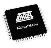
ATMEGA128A-AU 8-bit Microcontrollers - MCU 128K Flash 4K EEPROM 4K SRAM 53 IO Pins
Introduction

The Atmel® ATmega128A is a low-power CMOS 8-bit microcontroller based on the AVR® enhanced RISC architecture. By executing powerful instructions in a single clock cycle, the ATmega128A achieves throughputs close to 1MIPS per MHz. This empowers system designer to optimize the device for power consumption versus processing speed.
ATMEGA128A-AU Overview
The Atmel® ATmega128A is an 8-bit CMOS microcontroller with low power consumption based on the AVR® improved RISC architecture. The ATmega128A provides near-1MIPS per MHz throughput by executing strong instructions in a single clock cycle. The system designer is now able to tune the gadget for power consumption vs processing speed.
Detailed Description
The ATmega128A provides the fllowing features: 128Kbytes of In-System Programmable Flash withRead- While-Write capabilities, 4Kbytes EEPROM, 4Kbytes SRAM, 53 general purpose /0 lines, 32 general purpose working registers, Real Time Counter (RTC), four flexible Timer/Counters with compare modes and PWM, 2 USARTs, one byte oriented Two-wire Serial Interface, an 8-channel, 10-bit ADC with optional differential input stage with programmable gain, programmable Watchdog Timer with Internal Osillator, one SPI serial port, IEEE std. 1149.1 compliant JTAG test interface, also used for accessing the On-chip Debug system and programming and six sofware selectable power saving modes. The Idle mode stops the CPU while allowing the SRAM, Timer/Counters, SPI port, and interrupt system to continue functioning. The Power-down mode saves the register contents but freezes the Oscillator, disabling all other chip functions until the next interrupt or Hardware Reset. In Power-save mode, the asynchronous timer continues to run, allowing the user to maintain a timer base while the rest of the device is sleeping. The ADC Noise Reduction mode stops the CPU and all /0 modules except Asynchronous Timer and ADC, to minimize switching noise during ADC conversions. In Standby mode, the Crystal/Resonator Ocillator is running while the rest of the device is sleeping. This allows very fast start-up combined with low power consumption. In Extended Standby mode, both the main Oscillator and the Asynchronous Timer continue to run.
The ATmega128A AVR is supported with a full suite of program and system development tools including: C compilers, macro assemblers, program debugger/simulators, in-circuit emulators, and evaluation kits.
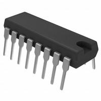
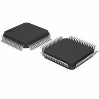
ATMEGA128A-AU Pinout

ATMEGA128A-AU CAD Model
Symbol

Footprint

3D-Model

ATMEGA128A-AU Features
• High-performance, Low-power Atmel AVR 8-bit Microcontroller
• Advanced RISC Architecture
–133 Powerful Instructions
–Most Single-clock Cycle Execution
–32 × 8 General Purpose Working Registers + Peripheral Control Registers – Fully Static Operation
– Up to 16MIPS Throughput at 16MHz
– On-chip 2-cycle Multiplier
• High Endurance Non-volatile Memory segments
– 128Kbytes of In-System Self-programmable Flash program memory
– 4Kbytes EEPROM – 4Kbytes Internal SRAM
– Write/Erase cycles: 10,000 Flash/100,000 EEPROM
– Data retention: 20 years at 85°C/100 years at 25°C(1)
– Optional Boot Code Section with Independent Lock Bits
• In-System Programming by On-chip Boot Program
• True Read-While-Write Operation
– Up to 64 Kbytes Optional External Memory Space
– Programming Lock for Software Security
– SPI Interface for In-System Programming
• JTAG (IEEE std. 1149.1 Compliant) Interface
– Boundary-scan Capabilities According to the JTAG Standard
– Extensive On-chip Debug Support
– Programming of Flash, EEPROM, Fuses and Lock Bits through the JTAG Interface
•I/O and Packages
– 53 Programmable I/O Lines
– 64-lead TQFP and 64-pad QFN/MLF
• Operating Voltages – 2.7 - 5.5V
• Speed Grades – 0 - 16MHz
ATMEGA128A-AU Applications
Consumer electronics
Wireless communication
Imaging products
Internet application
ATMEGA128A-AU Equivalents
STM32F407VGT6: This microcontroller from STMicroelectronics offers a 32-bit ARM Cortex-M4 core, 1MB flash memory, 192KB SRAM, and various communication interfaces.
PIC32MX795F512L: This microcontroller from Microchip Technology features a 32-bit MIPS M4K core, 512KB flash memory, 128KB RAM, and a wide range of peripherals.
LPC1768FBD100: This microcontroller from NXP Semiconductors offers a 32-bit ARM Cortex-M3 core, 512KB flash memory, 64KB SRAM, and extensive peripheral options.
ATMEGA128A-AU Functional Block Diagram
![R`Z3UL3RCY`E[`D]~B_{669](https://www.xinshop.com/upload/image/content/20231207/d5f089c14b40e485071202ae80dbd1b0.png "d5f089c14b40e485071202ae80dbd1b0.png")
ATMEGA128A-AU Package Dimension

Related articles
Specifications
- Manufacturer :
- Microchip Technology
- Product Category :
- Microcontrollers
- # I/Os (Max) :
- 53
- Additional Feature :
- IT ALSO OPERATES 8MHZ AT MINI 2.7V
- Address Bus Width :
- 16
- Base Part Number :
- ATMEGA128A
- Base Product Number :
- ATMEGA128
- Bit Size :
- 8
- Brand :
- Microchip Technology / Atmel
- Clock Freq :
- 16(MHz)
- Connectivity :
- EBI/EMI, I2C, SPI, UART/USART
- Contact Plating :
- Tin
- Core Processor :
- AVR
- Core Size :
- 8-Bit
- CPU Family :
- AVR RISC
- DAC Channels :
- yes
- Data Bus Width :
- 8B
- Data Converter :
- A/D 8x10b
- Data Converters :
- A/D 8x10b
- Device Core :
- AVR
- Device Core Size :
- 8(b)
- DMA Channels :
- No
- EEPROM Size :
- 4K x 8
- External Data Bus Width :
- 8
- Factory Lead Time :
- 7 Weeks
- Frequency :
- 16MHz
- Has ADC :
- yes
- Height Seated (Max) :
- 1.2mm
- Instruction Set Architecture :
- RISC
- Interface :
- EBI/EMI, I2C, SPI, UART, USART
- Interface Type :
- JTAG/SPI/TWI/USART
- Interfaces :
- JTAG/SPI/TWI/USART
- JESD-30 Code :
- S-PQFP-G64
- JESD-609 Code :
- e3
- Lead Free :
- Lead Free
- Length :
- 14 mm
- Manufacturer :
- Microchip
- Manufacturer Package Identifier :
- 64A
- Maximum Expanded Memory Size :
- 64KB
- Maximum Operating Temperature :
- + 85 C
- Memory Size :
- 128kB
- Mfr :
- Microchip Technology
- Minimum Operating Temperature :
- - 40 C
- Moisture Sensitivity Level (MSL) :
- 3 (168 Hours)
- Mount :
- Surface Mount
- Mounting :
- Surface Mount
- Mounting Style :
- SMD/SMT
- Mounting Type :
- Surface Mount
- MSL :
- MSL 3 - 168 hours
- Number of ADC Channels :
- 8 Channel
- Number of I/O :
- 53
- Number of I/O Lines :
- 53
- Number of I/Os :
- 53 I/O
- Number of Pins :
- 64
- Number of Terminals :
- 64
- Number of Terminations :
- 64
- Number of Timers - General Purpose :
- 4
- Number of Timers/Counters :
- 4
- Operating Supply Voltage (Max) :
- 5.5(V)
- Operating Supply Voltage (Min) :
- 2.7(V)
- Operating Supply Voltage (Typ) :
- 3.3/5(V)
- Operating Temp Range :
- -40C to 85C
- Operating Temperature :
- -40°C~85°C TA
- Operating Temperature (Max) :
- 85C
- Operating Temperature (Min) :
- -40C
- Operating Temperature Classification :
- Industrial
- Oscillator Type :
- Internal
- Package :
- Tape and Reel (TR);Cut Tape (CT);Digi-Reel®;
- Package / Case :
- 64-TQFP
- Package Shape :
- Square
- Package Type :
- TQFP
- Packaging :
- Tape and Reel (TR)
- Part Status :
- Active
- Pbfree Code :
- yes
- Peak Reflow Temperature (Cel) :
- 260
- Peripherals :
- Brown-out Detect/Reset, POR, PWM, WDT
- Pin Count :
- 64
- Power Supplies :
- 3/5V
- Product :
- MCU
- Product Category :
- 8-bit Microcontrollers - MCU
- Product Status :
- Active
- Product Type :
- 8-bit Microcontrollers - MCU
- Program Memory Size :
- 128KB 64K x 16
- Program Memory Type :
- Flash
- Programmable :
- yes
- Published :
- 2003
- PWM Channels :
- yes
- Qualification :
- -
- Qualification Status :
- Not Qualified
- Rad Hardened :
- No
- Radiation Hardening :
- No
- RAM (bytes) :
- 4096
- RAM Size :
- 4K x 8
- Reach Compliance Code :
- Compliant
- REACH SVHC :
- No SVHC
- RoHS :
- Details
- RoHS Status :
- ROHS3 Compliant
- ROM (words) :
- 65536
- ROM Programmability :
- Flash
- Seated Height-Max :
- 1.2 mm
- Series :
- AVR® ATmega
- Speed :
- 16MHz
- Supplier Device Package :
- 64-TQFP (14x14)
- Supply Current-Max :
- 19 mA
- Supply Voltage :
- 5V
- Supply Voltage-Max (Vsup) :
- 5.5V
- Surface Mount :
- yes
- Temperature Grade :
- Industrial
- Terminal Finish :
- Matte Tin (Sn)
- Terminal Form :
- Gull wing
- Terminal Pitch :
- 0.8mm
- Terminal Position :
- QUAD
- Time@Peak Reflow Temperature-Max (s) :
- 40
- Total Internal Ram Size :
- 4KB(kB)
- Tradename :
- AVR
- uPs/uCs/Peripheral ICs Type :
- MICROCONTROLLER, RISC
- Voltage - Supply (Vcc/Vdd) :
- 2.7V~5.5V
- Watchdog Timer :
- yes
- Width :
- 14 mm
Datasheets
- Datasheets
- ATMEGA128A-AU
- Share this post
-


Frequently Asked Questions
What is the use of ATmega controller?
The ATmega series of microcontrollers is suited for use in a variety of arduino and other development-type applications. ATmega microcontrollers are typically 8-bit microcontrollers with Harvard Architecture based on Reduced Instruction Set (RISC).
What language does ATMega use?
The ATMEGA microcontrollers, including the ATMEGA128A-AU, can be programmed using the C/C++ programming language. The microcontrollers are typically programmed using the Arduino IDE, which provides a simplified programming environment and a library of functions to interact with the hardware peripherals of the microcontroller. However, it is also possible to program the ATMEGA microcontrollers using other programming languages such as assembly language or even higher-level languages like Python or JavaScript, although these require more advanced development tools and knowledge of the microcontroller’s architecture. The choice of programming language ultimately depends on the specific requirements and preferences of the developer.
Related Articles

DRV8908QPWPRQ1 Motor Driver Datasheet,Pinout,Specification
LIS3DHTR Accelerometer for Your Projects
TMS320F28335PGFA Datasheet, Pinout, Specification
NE555 vs NE5532:Comparison for Electronics Enthusiasts
NE5532 vs OPA1612 Op-Amp: Choosing Your Right One
STM32 STM32G070RBT6 Datasheet for Embedded Systems
ADM2587EBRWZ RS-485/RS-422 Transceiver:Datasheet
CH340 vs CP2102 vs CH341 vs FT232 Differences
LM324 Op amp Pinout,Datasheet,Spec,Circuit:How to Test LM324?
What Is The Difference Between 7812 And 7805?PDF,Price,Pinout
-
1,000+Daily Order Quantity
-
2,500,000+Alternative Parts
-
2,200+Worldwide Manufacturers
-
10,000 ㎡In-stock Warehouse


