STM32F446 Microcontrollers: Circuit, Pinout, and Datasheet
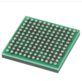
256KB 256K x 8 FLASH ARM® Cortex®-M4 32-Bit Microcontroller STM32F4 Series STM32F446 144 Pin 180MHz 3.3V 144-UFBGA
The STM32F446 devices are built around the high-performance Arm® Cortex®-M4 32-bit RISC processor, which runs at up to 180 MHz. This article mainly introduces circuit, pinout,datasheet and other detailed information about STMicroelectronics STM32F446.
Catalog
STM32F446 Description
STM32F446 Pinout
STM32F446 CAD Model
STM32F446 Features
STM32F446 Functional Block Diagram
STM32F446 Power Supply Scheme
STM32F446 Applications
STM32F446 Package
STM32F446 VS STM32F407: Difference
Specifications
Datasheet PDF
STM32F446 Description
The STM32F446 devices are built around the high-performance Arm® Cortex®-M4 32-bit RISC processor, which runs at up to 180 MHz. All Arm® single-precision data-processing instructions and data formats are supported by the Cortex-M4 core's floating-point unit (FPU) single precision. It also includes a memory protection unit (MPU) to improve program security and a full set of DSP commands.
High-speed embedded memories (Flash memory up to 512 Kbytes, 128 Kbytes of SRAM), up to 4 Kbytes of backup SRAM, and a comprehensive range of upgraded I/Os and peripherals are all included in the STM32F446 devices, which are coupled to two APB buses, two AHB buses, and a 32-bit multi-AHB bus matrix.
Three 12-bit ADCs, two DACs, a low-power RTC, twelve general-purpose 16-bit timers, two PWM timers for motor control, and two general-purpose 32-bit timers are available on all devices.
STM32F446 Pinout
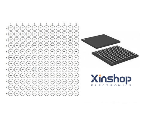
STM32F446 CAD Model
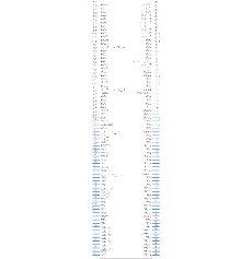
Symbol
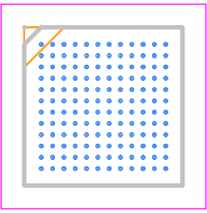
Footprint
3D Model
STM32F446 Features
• Core: Arm® 32-bit Cortex®-M4 CPU with FPU, Adaptive real-time accelerator (ART Accelerator) allowing 0-wait state execution from Flash memory, frequency up to 180 MHz, MPU, 225 DMIPS/1.25 DMIPS/MHz (Dhrystone 2.1), and DSP instructions
• Memories
– 512 Kbytes of Flash memory
– 128 Kbytes of SRAM
– Flexible external memory controller with up to 16-bit data bus: SRAM, PSRAM, SDRAM/LPSDR SDRAM, NOR/NAND Flash memories
– Dual-mode QuadSPI interface
• LCD parallel interface, 8080/6800 modes
• Clock, reset and supply management
– 1.7 V to 3.6 V application supply and I/Os
– POR, PDR, PVD and BOR
– 4 to 26 MHz crystal oscillator
– Internal 16 MHz factory-trimmed RC (1% accuracy)
– 32 kHz oscillator for RTC with calibration
– Internal 32 kHz RC with calibration
• Low power
– Sleep, Stop and Standby modes
– VBAT supply for RTC, 20×32 bit backup registers plus optional 4 KB backup SRAM
• 3×12-bit, 2.4 MSPS ADC: up to 24 channels and 7.2 MSPS in triple interleaved mode
• 2×12-bit D/A converters
• General-purpose DMA: 16-stream DMA controller with FIFOs and burst support
• Up to 17 timers: 2x watchdog, 1x SysTick timer and up to twelve 16-bit and two 32-bit timers up to 180 MHz, each with up to four IC/OC/PWM or pulse counter
• Debug mode
– SWD and JTAG interfaces
– Cortex®-M4 Trace Macrocell™
• Up to 114 I/O ports with interrupt capability
– Up to 111 fast I/Os up to 90 MHz
– Up to 112 5 V-tolerant I/Os
• Up to 20 communication interfaces
– SPDIF-Rx
– Up to 4 × I2C interfaces (SMBus/PMBus)
– Up to four USARTs and two UARTs (11.25 Mbit/s, ISO7816 interface, LIN, IrDA, modem control)
– Up to four SPIs (45 Mbits/s), three with muxed I2S for audio class accuracy via internal audio PLL or external clock
– 2 x SAI (serial audio interface)
– 2 × CAN (2.0B Active)
– SDIO interface
– Consumer electronics control (CEC) I/F
• Advanced connectivity
– USB 2.0 full-speed device/host/OTG controller with on-chip PHY
– USB 2.0 high-speed/full-speed device/host/OTG controller with dedicated DMA, on-chip full-speed PHY and ULPI
– Dedicated USB power rail enabling on-chip PHYs operation throughout the entire MCU power supply range
• 8- to 14-bit parallel camera interface up to 54 Mbytes/s
• CRC calculation unit
• RTC: subsecond accuracy, hardware calendar
• 96-bit unique ID
Specifications
STMicroelectronics STM32F446ZCH6 technical specifications, attributes, parameters and parts with similar specifications to STMicroelectronics STM32F446ZCH6.
STM32F446 Functional Block Diagram
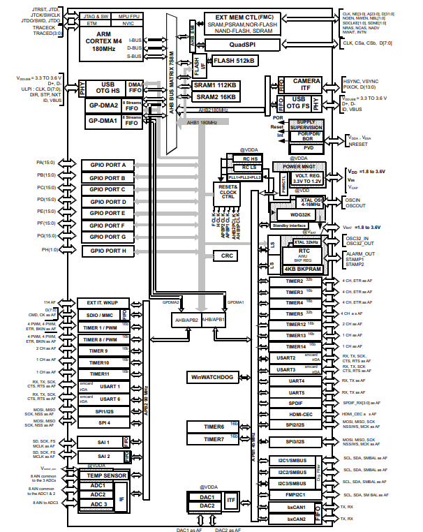
Functional Block Diagram
STM32F446 Loading Capacitor
The loading conditions used for pin parameter measurement are shown in the pic below.
Pin Loading Conditions
STM32F446 Pin Input Voltage
The input voltage measurement on a pin of the device is described in the pic below.
Pin Input Voltage
STM32F446 Power Supply Scheme
Power Supply Scheme
1. VDDA and VSSA must be connected to VDDand VSS, respectively.
2. VDD USB is a dedicated independent USB power supply for the on-chip full-speed OTG PHY module and associated DP/DM GPIOs. Its value is independent of the VDD and VDDA values, but must be the last supply to be provided and the first to disappear. If VDD is different from VDD USB and only one on-chip OTG PHY is used, the second OTG PHY GPIOs (DP/DM) is still supplied at VDD USB (3.3V).
3. VDD USB is available only on WLCSP81, UFBGA144 and LQFP144 packages. For packages where VDDUSB pin is not available, it is internally connected to VDD.
4. VCAP_2 pad is not available on LQFP64.
STM32F446 Applications
• Industry
• Technology
• Internet-of-Things (IoT)
• Extensive Clock Gating
• Flexible Sleep Mode
• Motor Drive and Application Control
• Medical Equipment
• Industrial Applications: PLC, Inverters, Circuit Breakers
• Printers, and Scanners
• Alarm Systems, Video Intercom, and HVAC
• Home Audio Appliances
STM32F446 Package
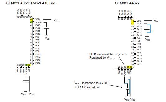
Package
STM32F446 VS STM32F407: Difference
A Comparison of STM32F446 and STM32F407 Microcontrollers
Architecture and Performance:
Both the STM32F446 and STM32F407 microcontrollers are based on the ARM Cortex-M4 core, providing high performance and efficient processing capabilities. They feature a 32-bit RISC architecture, offering a balance between power consumption and computational power.
The STM32F446 operates at a maximum frequency of 180 MHz, while the STM32F407 can reach up to 168 MHz. This slight difference in clock frequency does not significantly impact their overall performance.
Memory and Storage:
The STM32F446 and STM32F407 microcontrollers offer various memory options to cater to different application requirements. They both have Flash memory for program storage and RAM for data storage.
The STM32F446 provides up to 512 KB of Flash memory and 128 KB of SRAM, while the STM32F407 offers up to 1 MB of Flash memory and 192 KB of SRAM. This additional memory in the STM32F407 makes it suitable for applications that require larger program or data storage.
Peripherals and Connectivity:
Both microcontrollers come with a rich set of peripherals and connectivity options, allowing for seamless integration with external devices and sensors. They offer multiple UART, SPI, and I2C interfaces, as well as USB, CAN, and Ethernet connectivity.
However, the STM32F407 provides some additional features, such as an integrated audio digital-to-analog converter (DAC) and an external memory interface (EMI), which allows for easy interfacing with external memory devices.
Power Efficiency:
Power efficiency is a crucial factor in embedded system design. Both the STM32F446 and STM32F407 microcontrollers feature low-power modes, allowing for efficient power management and extended battery life in battery-powered applications.
Development Ecosystem:
The STM32 family enjoys strong community support and a mature development ecosystem. Both the STM32F446 and STM32F407 microcontrollers are supported by the STM32Cube software development platform, which provides a comprehensive set of tools, middleware, and software libraries.
Conclusion:
The STM32F446 and STM32F407 microcontrollers are powerful and versatile devices suitable for a wide range of embedded system applications. While they share many similarities, they also have some key differences in terms of memory, peripherals, and connectivity options.
The STM32F446 is an excellent choice for applications that require a balance between performance and cost, with sufficient memory and connectivity options. On the other hand, the STM32F407 offers additional memory and features, making it suitable for more demanding applications that require larger program or data storage and advanced connectivity options.
Ultimately, the choice between the STM32F446 and STM32F407 microcontrollers depends on the specific requirements of the application at hand. It is recommended to carefully evaluate the project needs and consult the official documentation and community support to make an informed decision.
Datasheet PDF
Download datasheets and manufacturer documentation for STMicroelectronics STM32F446ZCH6

Frequently Asked Questions


