DS1302: A Versatile Real-Time Clock (RTC) for Embedded Systems
Introduction
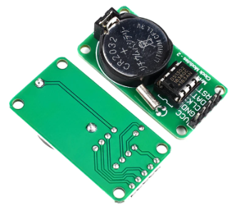
The DS1302 is a highly integrated real-time clock (RTC) chip that provides accurate timekeeping for embedded systems. It features a low power consumption, a wide operating voltage range, and a simple interface. This article explores the features, applications, and interfacing of the DS1302 arduino.

DS1302 Features
* Real-time clock with seconds, minutes, hours, day, date, month, and year
* Automatic leap year compensation
* Battery backup for continuous operation during power outages
* Low power consumption (less than 500nA in standby mode)
* Wide operating voltage range (2.0V to 5.5V)
* I²C interface for easy communication
DS1302 Applications
The DS1302 is widely used in various applications, including:
* Embedded systems
* Data loggers
* Time-stamped systems
* Security systems
* Medical devices
DS1302 Interfacing
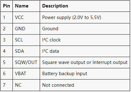
The DS1302 communicates via the I²C bus. It has a 7-bit slave address (0x68). The following table shows the pin configuration:

DS1302 Timekeeping
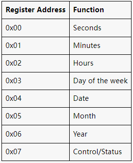
The DS1302 maintains time and date information in eight registers. These registers can be read or written via the I²C interface. The following table shows the register addresses and their corresponding functions:

DS1302 Battery Backup

The DS1302 has a built-in battery backup circuit that allows it to continue operating even when the main power supply is disconnected. The battery backup voltage is typically provided by a 3V lithium coin cell battery.
ds 1302 datasheet can be found at the end of the article.
STM32+RTC(DS1302)Real-time clock design
Materials:
* STM32 microcontroller board
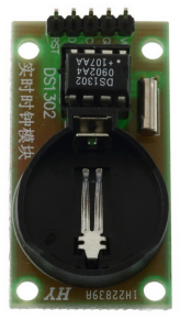
* DS1302 real-time clock module
* I2C interface (optional)
* Battery (for backup power)
Schematic:
Connect the DS1302 module to the STM32 board via I2C or SPI interface. The specific connections may vary depending on the microcontroller and RTC module used.
Configuration:
1. **Enable I2C/SPI:** Configure the I2C/SPI peripheral on the STM32 microcontroller to communicate with the DS1302 module.
2. **Set RTC time:** Initialize the DS1302 module and set the current time and date using the appropriate I2C/SPI commands.
3. **Enable backup power:** Connect a battery to the DS1302 module to provide backup power in case of power loss.
4. **Configure interrupts (optional):** If desired, configure interrupts on the STM32 microcontroller to receive notifications from the DS1302 module (e.g., alarm triggers).
Code:
The following code snippet shows an example of how to initialize the DS1302 module and set the time:
```c
#include "stm32f1xx_hal.h"
#include "ds1302.h"
// Initialize I2C communication
HAL_I2C_Init(&hi2c);
// Initialize DS1302 module
DS1302_Init();
// Set current time and date
DS1302_SetTime(12, 30, 0);
DS1302_SetDate(2023, 3, 15);
```
Usage:
Once the RTC is configured, you can use it to:
* Keep track of the current time and date
* Set alarms and interrupts
* Calibrate the RTC using an external clock source
Additional Considerations:
* The DS1302 module has a limited battery life. Replace the battery periodically to ensure uninterrupted operation.
* The accuracy of the RTC depends on the crystal oscillator used in the module. Consider using a high-quality crystal for better accuracy.
* If using I2C, ensure that the I2C pull-up resistors are connected properly
Conclusion
The ds1302 rtc is a versatile and reliable real-time clock chip that is ideal for embedded systems and various timekeeping applications. Its low power consumption, wide operating voltage range, and simple I²C interface make it a popular choice for designers. By understanding its features and interfacing, engineers can easily incorporate the DS1302 into their projects to achieve accurate timekeeping and data logging capabilities.


