2N7000 Vs 2N7002 Transistor Difference Comparison
Hi, friends, when looking at 2N7000 Vs 2N7002 these two components, you might have a question: Are They Replaceable? So this post will make a Comparison about their features
Introduction:
Hi, friends. The 2N7000 and 2N7002 are two popular MOSFET (Metal-Oxide-Semiconductor Field-Effect Transistor) devices widely used in various electronic circuits. While they may seem similar at first glance, there are distinct differences between these two components that make them suitable for different applications. In this article, we will delve into the details of the 2N7000 and 2N7002 transistors, highlighting their specifications, characteristics, and their respective applications.
2N7000 Vs 2N7002 Description
Overview of 2N7000: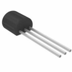
The 2N7000 is an N-channel enhancement mode MOSFET transistor. It is designed to operate with low voltage and low current requirements. The device features a maximum drain-source voltage (VDS) of 60 volts and a continuous drain current (ID) of 200 mA. With a low threshold voltage (VGS(th)) of around 2-4 volts, the 2N7000 is ideal for low-power applications that require efficient switching capabilities. It is commonly used in small signal amplification, low voltage switching, and general-purpose applications.
Overview of 2N7002: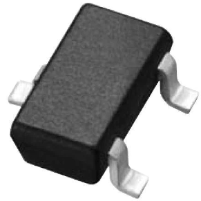
Similar to the 2N7000, the 2N7002 is also an N-channel enhancement mode MOSFET transistor. However, it offers some distinct differences in terms of its specifications. The 2N7002 has a higher drain-source voltage rating, with a VDS of 60 volts, making it suitable for applications that require higher voltage tolerances. It also has a slightly higher continuous drain current rating, with an ID of 300 mA. Like the 2N7000, the 2N7002 has a low threshold voltage, typically ranging from 1-3 volts. This makes it suitable for low-power devices and switching applications.
2N7000 Vs 2N7002 Pinout
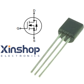
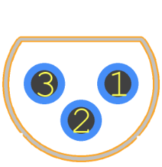
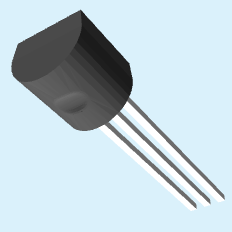
2N7000 Vs 2N7002 CAD-Model
Symbol
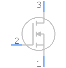
Footprint
3D-Model
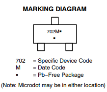
2N7000 Vs 2N7002 Diagram
2N7000 Vs 2N7002 Equivalent
2N7000 Vs 2N7002 Applications
2N7000 Vs 2N7002 Application Circuit
2N7000 Vs 2N7002 Package Dimension
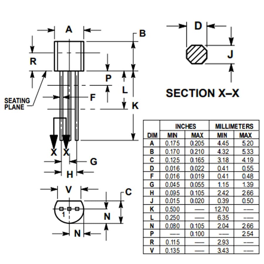
*If you want to read the technical document pdf 2N7000 Datasheet and 2N7002 Datasheet,
swipe to the end of the article and click to see datasheet.
2N7000 Vs 2N7002 Working and function
Working Principle:
Both the 2N7000 and 2N7002 transistors are N-channel enhancement mode MOSFETs. MOSFETs are three-terminal devices with a gate (G), drain (D), and source (S) terminals. They operate based on the principle of the electric field effect controlled by the voltage applied to the gate terminal.
When a positive voltage is applied to the gate terminal with respect to the source terminal, it creates an electric field that attracts electrons towards the channel between the drain and source. The channel gets effectively formed, allowing current to flow from the drain to the source. This is known as the "on" state or the conducting state.
On the other hand, when the voltage at the gate terminal is lower than a certain threshold voltage, typically referred to as VGS(th), the channel becomes less conductive, and the transistor enters the "off" state or non-conducting state. In this state, the current flow between the drain and source is minimal.
Function:
The primary function of the 2N7000 and 2N7002 transistors is to amplify and switch electronic signals. They are widely used in various applications where precise control of electrical signals is required.
Amplification: In amplification applications, the transistors are used to amplify weak electrical signals, such as audio or radio frequency signals, to a higher power or voltage level. By controlling the voltage applied to the gate terminal, the transistors allow precise amplification of the input signals.
Switching: MOSFET transistors are commonly used as switches in electronic circuits. They can efficiently control the flow of current based on the voltage applied to the gate terminal. When the gate voltage exceeds the threshold voltage, the transistor turns on, allowing current to flow from the drain to the source. Conversely, when the gate voltage is below the threshold voltage, the transistor turns off, interrupting the current flow.
Protection: The 2N7000 and 2N7002 transistors can also be employed in various protection circuits, such as overvoltage protection and battery protection circuits. Their low threshold voltage and voltage rating make them suitable for safeguarding sensitive electronic components from excessive voltage or current.
Voltage Level Shifting: MOSFETs can also be used for level shifting applications, where they enable the translation of signals from one voltage level to another. By using appropriate biasing and control voltages, the transistors facilitate the translation of high-level signals to low-level signals or vice versa.
Overall, the 2N7000 and 2N7002 transistors serve as versatile components in electronic circuits, allowing efficient amplification, switching, and protection of electrical signals. Their compact size, low power requirements, and compatibility with various integrated circuits make them popular choices among engineers and hobbyists working on a wide range of electronic projects.
2n7000 2n7002 Differences and Applications:
1. Voltage Rating: One of the key differences between the 2N7000 and 2N7002 is their voltage ratings. The 2N7002 has a higher drain-source voltage rating of 60 volts, compared to the 2N7000, which also has a VDS of 60 volts. This higher voltage rating makes the 2N7002 better suited for applications where a higher voltage tolerance is required.
2. Drain Current: Another significant difference lies in their continuous drain current ratings. The 2N7002 has a higher ID rating of 300 mA, while the 2N7000 has an ID rating of 200 mA. This higher current rating in the 2N7002 enables it to handle more current, making it suitable for applications demanding higher power requirements.
3. Gate-Source Threshold Voltage: The gate-source threshold voltage, VGS(th), is the voltage at which the MOSFET starts conducting. While both the 2N7000 and 2N7002 have low threshold voltages, the 2N7002 typically has a slightly lower VGS(th) compared to the 2N7000. This lower threshold voltage allows the 2N7002 to switch on and off more easily with lower control voltages, making it a good choice for low-power applications.
In terms of applications, the 2N7000 is commonly used in small signal amplification, low voltage switching, and general-purpose circuits. Its lower drain current rating and voltage tolerance make it suitable for low-power applications. On the other hand, the 2N7002, with its higher drain current and voltage ratings, is better suited for applications that require higher current handling and voltage tolerances, such as motor control, power management, and battery protection circuits.
Conclusion:
In summary, the 2N7000 and 2N7002 are both N-channel enhancement mode MOSFET transistors with similar characteristics. However, they differ in voltage rating, drain current handling, and gate-source threshold voltages. Understanding these differences is crucial in selecting the right transistor for a specific application. The 2N7000 is suitable for low-power applications, while the 2N7002 is better suited for applications that require higher voltage and current capabilities. By considering their unique specifications, engineers and hobbyists can choose the most appropriate transistor to optimize the performance of their electronic circuits.


